 English
 Español
 日本語

Selecting a HEPA mini-pleat filter for a cleanroom comes down to matching six specifications to the room's ISO class, airflow design and physical housing: efficiency grade, airflow rating and face velocity, initial pressure drop, frame type and depth, sealing method, and media compatibility with the process chemistry.
A defensible default for most pharmaceutical, electronics and medical-device cleanrooms is a H14 mini-pleat filter (99.995% at MPPS), 610 × 610 × 69 mm, aluminum frame, gel seal, rated at 0.45 m/s face velocity with initial pressure drop between 100 and 130 Pa. That configuration fits standard fan filter units and terminal housings, achieves ISO Class 5 with normal air change rates, and leaves comfortable margin on fan static pressure.
The decision sequence that follows this answer:
- Establish the ISO cleanliness class and derive the required efficiency grade.
- Calculate air changes per hour, total airflow, and the number of filter units needed.
- Check face velocity and pressure drop against the fan or FFU capability.
- Choose frame, depth and seal to suit the ceiling grid and the testing regime.
- Confirm media and separator materials against temperature, humidity, chemicals and outgassing limits.
- Specify factory testing, certification documentation and the site scan-test procedure.

What Makes a Mini-Pleat Filter Different
Construction
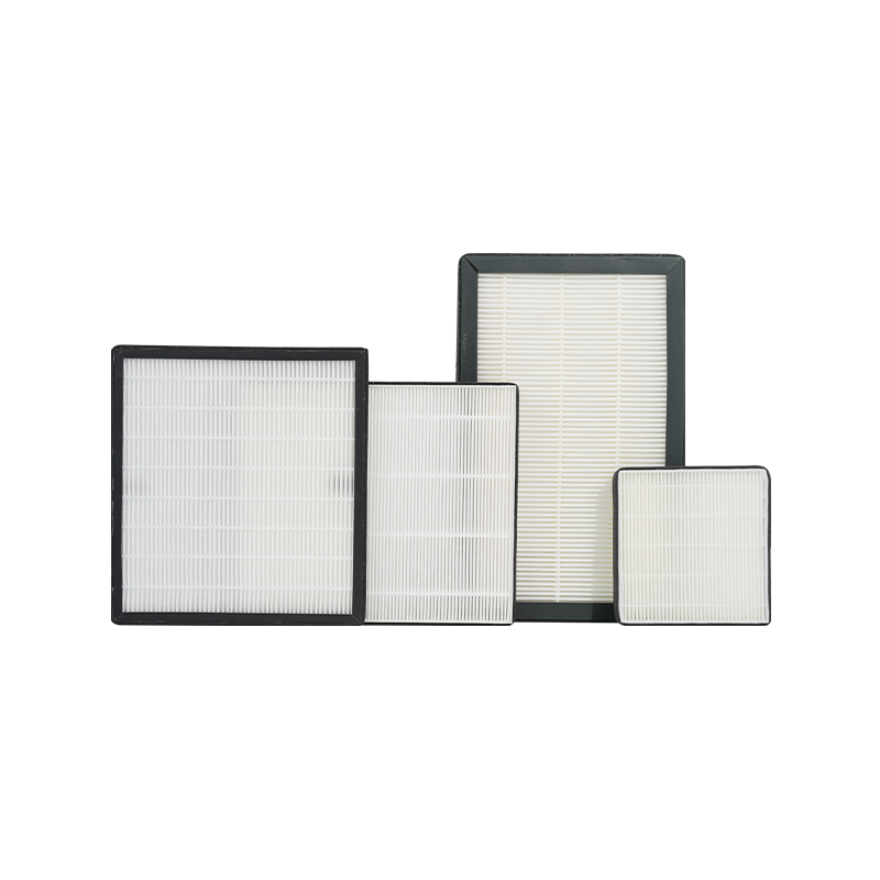
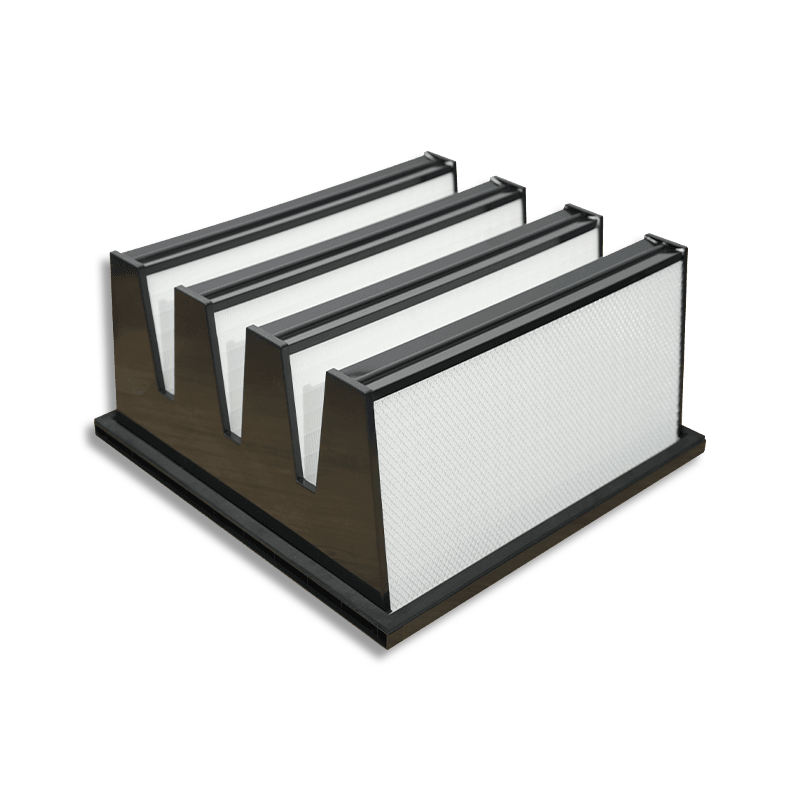
A mini-pleat HEPA uses glass fiber media folded into pleats 20–90 mm deep, held apart by hot-melt adhesive beads or thermoplastic separators applied every 15–25 mm. Classic deep-pleat filters instead use corrugated aluminum separators and pleats of 150 mm or more. The mini-pleat approach packs far more media into the same volume: a 610 × 610 × 69 mm mini-pleat holds 15–20 m² of media, versus roughly 9–11 m² for a 150 mm deep-pleat of the same face size.
Why That Matters for Cleanrooms
- Low media velocity.Spreading 1,000 m³/h across 18 m² of media gives a media velocity near 015 m/s, which is where glass fiber reaches its peak efficiency and lowest resistance.
- Shallow depth.A 69 mm or 90 mm body fits inside standard T-grid ceilings and FFU plenums where a 292 mm deep-pleat cannot.
- Uniform downstream velocity.Even pleat spacing produces a flat velocity profile, which is essential for unidirectional-flow zones where airflow uniformity is a qualification criterion.
- Low weight.Typically 4–7 kg for a 610 × 610 mm unit, simplifying ceiling support and single-person installation.
|
Typical characteristics of mini-pleat HEPA filters at standard 610 × 610 mm face size. |
|||
|
Depth |
Media Area |
Rated Airflow |
Initial Δp at Rated Flow |
|
50 mm |
10–13 m² |
600–900 m³/h |
110–150 Pa |
|
69 mm |
15–20 m² |
800–1,100 m³/h |
95–130 Pa |
|
90 mm |
20–26 m² |
1,000–1,400 m³/h |
80–110 Pa |
|
110–150 mm |
28–40 m² |
1,500–2,000 m³/h |
70–100 Pa |
Step One: Match Efficiency Grade to ISO Class
Understanding MPPS
EN 1822 rates HEPA filters at the Most Penetrating Particle Size, the diameter at which filtration is weakest because it falls between the range where diffusion dominates and the range where interception and impaction dominate. For standard glass fiber HEPA media this sits at 0.1 to 0.25 µm. Rating at MPPS is conservative by design: a filter that is 99.995% efficient at MPPS is more efficient than that at every other particle size, including at 0.3 µm where US IEST practice measures.
|
EN 1822 efficiency grades with penetration values and the cleanroom classes each typically serves. |
|||
|
Grade |
Overall Efficiency at MPPS |
Local Minimum Efficiency |
Typical Application |
|
H13 |
99.95% |
99.75% |
ISO 7–8, general clean areas |
|
H14 |
99.995% |
99.975% |
ISO 5–7, the mainstream choice |
|
U15 |
99.9995% |
99.9975% |
ISO 4, sensitive electronics |
|
U16 |
99.99995% |
99.99975% |
ISO 3 and cleaner, semiconductor |
|
U17 |
99.999995% |
99.9999% |
ISO 1–2, photolithography |
Mapping to Room Classification
|
ISO 14644-1 classes with particle limits, recommended filter grade, ceiling coverage and air change rates. |
||||
|
ISO Class |
Limit ≥0.5 µm (per m³) |
Filter Grade |
Ceiling Coverage |
Air Changes per Hour |
|
ISO 3 |
35 |
U16 |
80–100% |
400–600 |
|
ISO 4 |
352 |
U15–U16 |
60–90% |
300–500 |
|
ISO 5 |
3,520 |
H14 |
30–50% |
240–360 |
|
ISO 6 |
35,200 |
H13–H14 |
15–25% |
100–180 |
|
ISO 7 |
352,000 |
H13 |
10–15% |
60–90 |
|
ISO 8 |
3,520,000 |
H13 |
5–10% |
20–40 |
A useful rule: going one grade above the minimum requirement buys qualification margin at roughly 10–20% higher filter cost and 10–15 Pa more resistance. For GMP Grade A/B areas where a failed requalification is expensive, that margin is usually justified.
Step Two: Size the Airflow and Count the Filters
The Calculation
Total airflow (m³/h) = room volume (m³) × air changes per hour
Number of filters = total airflow ÷ rated airflow per filter
Worked Example: ISO 7 Filling Room
A room measuring 8 m × 6 m × 3 m = 144 m³ at 70 ACH requires 10,080 m³/h. Using 610 × 610 × 69 mm H14 units rated at 1,000 m³/h each, that is 10 to 11 filters. Round up to 12 and run each slightly below rated flow — resistance falls and service life extends. Ceiling coverage works out to 12 × 0.37 m² ÷ 48 m² = 9.3%, consistent with the ISO 7 guidance above.
Worked Example: ISO 5 Unidirectional Zone
Unidirectional zones are sized by velocity rather than air changes. For a 3 m × 2 m = 6 m² aseptic zone at 0.45 m/s, airflow is 6 × 0.45 × 3,600 = 9,720 m³/h. With 1,000 m³/h filters that is 10 units, and because the zone requires full coverage those units tile the entire 6 m² area. ISO 14644-4 and GMP Annex 1 practice place unidirectional velocity in the 0.36–0.54 m/s band, with 0.45 m/s the conventional design point.
Face Velocity Targets
- Unidirectional flow zones: 0.36–0.54 m/s, designed at 0.45 m/s.
- Non-unidirectional terminal filters: 1.0–1.5 m/sface velocity is acceptable since diffusion mixing is the goal.
- Design margin:select filters so the operating point sits at 70–85% of rated airflow, leaving headroom for the pressure rise across service life.
Step Three: Manage Pressure Drop and Service Life
Initial and Final Resistance
A clean H14 mini-pleat at rated flow typically reads 95–130 Pa. The accepted change-out point is twice initial resistance, or 400–500 Pa, whichever comes first. Between those points the filter is functioning at full efficiency — HEPA efficiency rises slightly as the filter loads, since captured particles narrow the effective fiber spacing.
Fan Energy
Fan power (kW) = airflow (m³/s) × Δp (Pa) ÷ (1,000 × efficiency)
For a single FFU moving 1,000 m³/h (0.278 m³/s) at 120 Pa with 55% efficiency, power is about 61 W. Across 100 FFUs running continuously that is 6.1 kW, or roughly 53,000 kWh per year. Selecting a 90 mm deep filter at 90 Pa instead of a 50 mm at 130 Pa cuts that figure by around 30%, which is often the largest single lever on cleanroom operating cost.
Protecting the Investment With Pre-Filtration
HEPA elements last 3 to 10 years when properly protected, and the protection is what determines where in that range a given installation lands. Specify the upstream train as:
- G4 / ISO Coarse pre-filterat the outdoor air intake, changed every 3 months.
- F7–F9 / ISO ePM1 medium filterin the AHU, changed every 6–12 months.
- F9 or H11 secondary filterimmediately upstream of the terminal HEPA in critical suites.
A well-designed pre-filter train commonly triples terminal HEPA life, which matters because replacing a terminal filter in a qualified area also means re-scanning, re-balancing and documentation.
Step Four: Choose the Frame, Depth and Gasket
Frame Materials
|
Frame material options for HEPA mini-pleat filters and the conditions each suits. |
||
|
Material |
Temperature Limit |
Suited To |
|
Anodized aluminum |
70 °C |
General cleanroom ceilings, FFUs |
|
Stainless steel 304/316 |
100 °C+ |
GMP aseptic suites, VHP decontamination, washdown |
|
Galvanized steel |
80 °C |
Industrial cleanrooms, duct-mounted housings |
|
MDF / composite board |
60 °C |
Dry, cost-sensitive general clean areas |
|
Stainless with high-temp separators |
250–350 °C |
Depyrogenation tunnels, oven exhausts |
Sealing Method
The seal is where most real-world leakage occurs, so this choice deserves as much attention as the efficiency grade.
- Gel seal.A polyurethane or silicone gel channel on the filter frame engages a knife edge on the ceiling grid. Delivers the most reliable seal available, is re-sealable after removal, and is the standard for ISO 5 and cleaner. Gel depth of 10–15 mm is typical.
- Closed-cell neoprene or EPDM gasket.A compressed foam gasket 6–10 mm thick on one face. Well-suited to ISO 6–8 terminal housings and FFU applications with even clamping.
- Liquid seal (fluid seal).The frame edge dips into a trough of viscous fluid in the housing. Used where the seal must be verified continuously, such as containment exhaust.
Specify the seal and the grid together. A gel-seal filter needs a knife-edge grid, and a gasket filter needs a flat clamping frame — mismatched hardware is a common and avoidable source of installation delay.
Standard Sizes
Common metric faces are 305 × 610, 610 × 610, 610 × 1,220 and 1,220 × 1,220 mm, in depths of 50, 69, 90 and 110 mm. Imperial equivalents are 2' × 2' and 2' × 4'. Staying within these sizes keeps replacement units available on short lead times and avoids the tooling premium on custom builds.
Step Five: Match Media to the Process Environment
Media Types
- Standard borosilicate glass fiber.The default for H13–U16, stable to 70–80 °C, tolerant of normal humidity swings.
- Water-repellent (hydrophobic) glass fiber.Treated media for suites subject to VHP or hydrogen peroxide decontamination, humidified rooms, or wash-down protocols. Specify this whenever RH can exceed 80%.
- ePTFE membrane.Boron-free and chemically inert, with resistance typically 20–40% lower than glass at equal efficiency. The preferred choice for semiconductor fabs where boron outgassing and AMC are controlled, and increasingly used in energy-sensitive installations.
- High-temperature glass with ceramic separators.For depyrogenation tunnel outlets and sterilizing oven applications up to 350 °C.
Sealant and Separator Compatibility
The potting compound that bonds media to frame is usually polyurethane, good to about 70 °C, or silicone for higher temperature and chemical duty. For aseptic suites confirm that the sealant is compatible with the sanitizing agent in use, and that low-outgassing certification is supplied where AMC limits apply.
|
Recommended configurations by industry application. |
|||
|
Application |
Grade |
Frame / Seal |
Media |
|
Aseptic filling (Grade A) |
H14 |
Stainless / gel seal |
Hydrophobic glass |
|
Solid dosage manufacturing |
H13–H14 |
Aluminum / gasket |
Standard glass |
|
Semiconductor fab |
U15–U17 |
Aluminum / gel seal |
ePTFE membrane |
|
Medical device assembly |
H14 |
Aluminum / gasket |
Standard glass |
|
Hospital operating theatre |
H14 |
Aluminum / gel seal |
Hydrophobic glass |
|
Depyrogenation tunnel |
H14 |
Stainless / ceramic sealant |
High-temp glass |
Step Six: Specify Testing and Certification
Factory Testing
Every H13 and above unit should be individually tested and serial-numbered. For H14 and cleaner, EN 1822-4 requires a 100% oil-thread or scan test of the whole filter face, not merely an aggregate efficiency measurement. Require the following documents with each shipment:
- Individual test certificate showing serial number, measured overall efficiency, local minimum efficiency and initial Δp at rated flow.
- Scan-test map or confirmation of leak-free status per EN 1822-4.
- Declaration of materials for frame, media, sealant and gasket.
- Low-outgassing or boron-free statement where applicable.
On-Site Installed Leak Testing
Factory certification proves the filter; site scanning proves the installation. Per ISO 14644-3, introduce a challenge aerosol (PAO, DEHS or equivalent) upstream to a concentration of 10–100 µg/L, then scan the downstream face with a photometer or particle counter probe held 25–50 mm from the media, traversing at no more than 50 mm/s with overlapping passes.
- Scan the media face, the media-to-frame joint, the frame itself and the gasket or gel interface.
- The conventional acceptance limit is 01% of upstream concentrationfor H14 installations.
- Record airflow velocity at the same time and confirm uniformity within ±20% of the meanfor unidirectional zones.
Requalification Intervals
|
Typical periodic test intervals for installed HEPA filters by cleanroom classification. |
||
|
Test |
ISO 5 and Cleaner |
ISO 6–9 |
|
Installed leak (scan) test |
Every 6 months |
Every 12 months |
|
Airflow velocity / volume |
Every 6 months |
Every 12 months |
|
Particle count classification |
Every 6 months |
Every 12 months |
|
Pressure drop reading |
Continuous or monthly |
Monthly |
Installation Practices That Preserve Performance
- Keep filters in original packaging until the moment of installation, and unpack inside the cleanroom envelope where practical.
- Handle by the frame only. Media is fragile enough that finger pressure can open a pinhole that shows up on the scan test.
- Store and transport flat or on edge as marked, never resting on the media face.
- Clean the grid knife edge or clamping surface before seating, since a single particle of construction debris in a gel channel creates a measurable leak path.
- Tighten clamps evenly in a cross pattern, compressing gaskets to the manufacturer's stated percentage — usually 25–40% of free thickness.
- Verify airflow direction arrows before final fixing.
- Run the system for at least 30 minutes to flush residual particlesbefore scanning and classification.
Specification Checklist
Take this list to the supplier and require an answer against every line before comparing prices:
- Target ISO class and corresponding EN 1822 grade, stated as overall andlocal minimum efficiency.
- Design airflow per filter and the resulting face velocity, with the operating point at 70–85% of rated flow.
- Initial Δp at the actual design flow, not at the catalogue reference flow, plus the recommended final Δp.
- Exact face dimensions, depth and tolerance, confirmed against the ceiling grid or FFU drawing.
- Frame material, seal type and gasket compression specification.
- Media type, temperature and humidity limits, and chemical compatibility with the sanitization agent.
- Individual serial-numbered test certificate and EN 1822-4 scan confirmation.
- Replacement lead time and confirmation that the size is a standard catalogue item.